Friday, 3 October 2014

axCut moves home, AFRo comes alive

axCut + Man Cave


It's been a long summer, but the man cave is now virtually complete and last weekend, the laser cutter (axCut) got moved into its long-term home:


AFRo


Whilst I've spent most of the sun-lit hours building, the dark hours have recently been spent on a new project - building an assistive feeding robot (named AFRo) for the UK charity REMAP.  The goal is not dissimilar to the HelloSpoon project (see Indiegogo campaign), but with enough differences to require a new solution.

You can are welcome to read through my detailed Design Notes as the design progresses, but for instant gratification, here is the latest video:


The hardware/software are both open source and published on github - see links in the Design Notes document, or search for the AFRo repo.    Hardware is fully modelled in OpenSCAD and predominantly 3D printable.   Total parts cost is currently around £260.

Comments/ideas welcome, but please read the Design Notes first in case they're already answered.


AFRo mk2

Although the mk1 mechanical design is functional and meets the design parameters, it suffers from too much vibration at the spoon tip :(  No good having a robot that shakes your food off the spoon.  It's not serious enough to abandon mk1, but it does mean I'm already working on mk2 in parallel.  It'll re-use most of the software, as the axis configuration is logically unchanged.  Here's the design sketch:


Will put up a more detailed post reviewing the design changes/reasons when I have time.


Monday, 7 July 2014

Man Cave (aka axLab)

So... progress on the laser cutter, and a number of other projects, has stalled in recent months due to two major issues:

  1. We have a 3rd baby on the way, so I need to evict myself from my office and the dining room :)
  2. The dining table is not stable enough for the laser cutter, so it needs a strong trolley to stand on
The solution to number 1 is to finally get on and build a good size workshop (man cave) at the end of the garden.  Number 2 will be solved by building and installing a trolley in the new man cave.  Simples.

Latest progress:


Man Cave Requirements

My choices in design, materials and approach will probably make more sense if you know I've always been fascinated by architecture, nearly went into a career as an architect, am addicted to DIY and plan one day to build my own house.  As it happens, I've been sketching designs for a work-shop/garden studio for years (nearly 10), but the deadline imposed by point 1 above has forced me to finally settle on something.  This has also been the first year where we could actually afford to build it!

So, top-line requirements:
  • As big as I can get away with - subject to permitted development, building regs and my wife
  • Split into a "clean" area (home office, electronics) and a "dirty" area (everything else)
  • As close to maintenance free as possible
  • Visually appealing (inside and out)
  • Solid concrete floor
  • Fairly well insulated walls, whilst keeping the total wall thickness to <150mm and cost to minimum
  • Include a decking area for patio set, bbq, etc
  • Budget of £6k

Exterior Design

Given the dimensions of our garden (18m long x 9m wide), plus the substantial hedgerows down both sides, I settled on a width of 6.5m.  Permitted development caps the roof height at 2.5m.  Wife, building regs and convenient timber lengths set the depth at 2.5m.    Although I've tried to keep the design as simple as possible, I just couldn't bring myself to build a plain box - so I opted for a sloping and gently curved facade.

Quick specs (happy to provide more info if anyone is interested):
  • Foundation: 250mm hardcore, 50mm sand blinding, DPM, 120mm concrete slab
  • 2-course dwarf perimeter wall from concrete blocks
  • Timber studwork walls (2"x4" framing, 16 inch centres) with 12mm OSB outer sheeting and 12mm plasterboard inner skin.  Insulated with 80mm rockwool.
  • The whole building is wrapped in Tyvek building paper, then the roof, back and sides are clad in industrial steel siding (in a rather fetching Forest Green).
  • Front cladding, window frames and stable door are handmade in oak.  
  • Deck - There will be a 5.5m x 2m deck along the front of the building.  Am keeping it simple with a floating foundation (80mm of gravel), then pressure treated framing in 2"x2", covered in oak boards.


Oak

I have a minor obsession with oak...  it's an awesome material.  For this project, I managed to find a great source of 30mm kiln dried oak boards (100 - 200mm width, random lengths) for approx £850/m3.  Given the great price, I've elected to use this same material for cladding, windows, doors and decking.  However, this has meant profiling a LOT of boards to make the cladding - a table saw is pretty much essential for this job!  Fortunately, the money I saved in sourcing cheaper oak meant I could afford to buy a table saw (at last) - a tool that has been on my wish list for years.  


Interior

The interior will be divided into two areas, with a partition wall just to the right of the main door.  The smaller right hand space (1.5m x 2.3m) will be the clean office area.  The remaining space will be the workshop.  The surface of the concrete slab got a bit ruined by a downpour just as I was finishing laying the slab, so I added a thin screed to improve the floor finish.  Walls and ceiling will be plastered shortly, then I can start installing work benches, etc.  I've not yet settled on an interior layout - so more to come as that evolves.


Current Status

As of last night, I've finished the stable door, so the building is secure for the first time.  The double glazed units are due to arrive later this week, ready for me to finish the windows.  Jobs for the next week or so:
  • Finish the cladding
  • Build partition wall and pocket sliding door
  • Build deck
Once the office space is functional, I can relocate from the house and then my old office needs to be converted to a bedroom for my son.  T-minus 16 wks to baby no. 3....   plenty still to do!


Thursday, 16 January 2014

axCut Laser Cutter - cracked it! z axes working, honeycomb bed installed - lovely jubbly!


Have finished installing the z-axes drives along with the honeycomb bed, and it has made such a difference.  I've been able to run some test cuts and finely calibrate the focal point (to within 0.1mm).  The host comms also seems to be behaving better (I'm convinced it's my windows laptop causing issues).

So... here's a video of it all working together - and it is working extremely well.  The test cut in the video is based on a friends wedding invite, and has converted into just 2223 lines of gcode - nice and compact thanks to the bezier curves!

The finished cut is very, very good - comparing it to the commercial reference (from same design file) it's as good, if not better (less wobble to the edges).  The low feedrate I've used may also be a contributing factor, but I'm still feeling rather smug.

Still lots to do on the hardware side (enclosure, cable chain for air assist, a rigid trolley), but for now, I think I'll take some time to play with cutting stuff!


Monday, 13 January 2014

axCut Laser Cutter - first cuts; not quite epic fail

We have cutting!  and a lot of smoke - really must order the cladding and setup some extraction!  This is a proper "Tomorrows World" video, it doesn't quite go to plan, but nonetheless - there's definite progress:


The cutting paths were generated from SVG via a little converter program I wrote using the paper.js library.  The arduino/Marlin combo is processing the bezier curves (as demo'd in previous video), but now with the addition of laser on/off commands around each path.  Air assist working nicely, except when the airline is being burnt by the laser :(

Laser control and watercooling all working well - the watercooling pump runs continuously, but the radiator fans only kick in when the laser outlet water temp rises above 22 degrees C.  The watercooling system is very quiet, thanks to the excellent little pump (Phobya DC12-260).  The fans are also extremely quiet when they are running, but the water temps haven't gotten above 19 degrees as yet (ambient temp during testing was just under 18, thanks to doors/windows being open for the smoke).

Laser control commands include arm/disarm of the laser PSU, control of laser power (0-100%), laser on/off and a diagnostic output.  The laser power control is via high speed PWM (62KHz, using timer4).
Air assist will soon be integrated into the relay module, so it can controlled by the arduino (via a couple of G-codes).

Air assist clearly plays a big role in:
 - stopping fires!  (without the air assist, there's a persistent flame about the cutting point)
 - keeping crap away from the lens

I'm assuming cut quality will get much better once the honeycomb bed is installed (so smoke/heat isn't being contained under the work) and once the focal point is properly calibrated.  I did go on to adjust the bed and do some power/feedrate tests, some of which you can see in the video below.  After bed adjustment, the cutting kerf at optimal power/feedrate is approx 0.2mm... should still be able to get better than that.  There is also quite a bit of scorching around the cut line, hoping the honeycomb+air will dramatically reduce that.


TODO:
 - Order cladding
 - Install honeycomb bed
 - Finish wiring z axis
 - Calibrate focal point
 - Solve raft of pronsole errors when sending complex jobs - presumably some errors in my firmware extensions
 - Integrate air assist line into axes (i.e. an x-axis cable chain)
 - Design/order/build decent trolley


Wednesday, 8 January 2014

laser cutter references

other than BuildLog and Lasersaur main sites.... I've also borrowed/been inspired by several items from Daniel's blog: http://danielbauen.com/make/index.php/laser-cutter/

In particular, I've borrowed the design of my laser tube mounts and plan to implement something along these lines for the diode laser:

http://danielbauen.com/make/index.php/laser-cutter/laser-inline-red-laser-pointer-solution-without-using-an-extra-m/

I like the passive design (dropped into the beam by the lid opening), but I'd also like to be able to use the visible pointer with the lid closed - so I'm thinking a little servo to lower the diode and a s/w interlock to ensure the laser can't activate if the diode is down (maybe not the safest arrangement, but hopefully good enough).

axCut Laser Cutter - Y dual stepper homing and z axis drives

Have uploaded a quick overview video of the completed homing system for the dual Y stepper arrangement:


It uses a normal microswitch on one side (the Y2 side) and a linear hall effect sensor on the other (Y side).  Have updated my fork of the Marlin firmware to support this homing technique.  Calibration parameter is modified using M666 command (and M667 to read), values stored in EEPROM.

Homing algorithm:

  1. Home Y as per normal
  2. Disable Y2 stepper, disable endstops
  3. Measure hall reading and compare to calibration target
  4. If error big, move Y one step towards correct position and goto 3
  5. Enable Y2 stepper, enable endstops
I'm currently using 32x oversampling on the hall reading, with 5ms delay between reads, but there's still a load of sensor noise.  Doesn't help that the sensor is next to two stepper motors!  Works ok, just takes a few iterations to converge.  Will do for now.

Z axis drives fitted (uses Mendel90 z-couplings) and ready for wiring tonight.


Sunday, 5 January 2014

axCut Laser Cutter - X/Y axes working, laser calibrated

Now have both the X and Y axes working and have calibrated the optics using a mock tube to hold a visible laser diode.  The laser calibration technique may be of interest to others building laser cutters, as it means I can carefully calibrate the optics with the visible laser, then drop in the CO2 laser and be fairly confident the beam will follow the same path - will found how well this works in a few days when I fit and fire the CO2 laser!


and a quick demo of high feedrate with a lissajous pattern:


Up next:

  • Finish the water cooling system
  • Integrate the laser power supply
  • Fit and test fire the CO2 laser
  • Finish the z-axes (waiting for stepper motors to arrive)
  • Add RPI host controller and touch screen
  • Order cladding


Friday, 27 December 2013

axCut WIP - X/Y axes and optics nearly complete

First spool of plastic down, and the mechanical elements of the x/y axes are virtually complete, as are the various brackets for the optics (mirror and laser holders).  


Steps to get x/y finished:
  • Design/print limit switch brackets (for microswitches)
  • Tweak and re-print x-carriage plate - holes for the v-groove wheel bolts are too tight, preventing correct alignment/pressure on the rails.
  • Finish design of cable-chain for y-carriage (have a basic design started, needs refinement)
  • Wire it up to RAMPS board - test!


Steps to get optics finished:
  • Re-design/print fixed mirror holder - current design is not sufficiently rigid; allows for some flex/vibration of the mirror
  • Fit laser tube (already tested, brackets work well)
  • Fit and align mirrors
  • Sort out water cooling (big-ish job!)
  • Wire it up, test it!


 Will do another post about some of the 20x20 fixings I've developed along the way, you can see some of them in the pictures above:

  • Printed nut carrier (inspired by: http://www.thingiverse.com/thing:28788) - used extensively, must have made over 200 of these by now!
  • Drop-in square nut carrier (for when you forget to insert a t-nut carrier and can't be bothered to dismantle the frame to slide one in!) - this is still WIP, as the current design is a right pain to use
  • Snap-fitting - these do not require a t-nut (or equiv), they push into the 20x20 slot and then tighten into place with an M4 screw (you can see these on the photo of the ATX PSU brackets)

After the above, it's on to assembling the bed and associated z-axes drives.

Saturday, 16 November 2013

Laser Cutter Build

Early days, but I'm currently spending a LOT of hours on a laser cutter build - heavily inspired by BuildLog 2.x and Lasersaur.  All of the design is in OpenSCAD, building on the excellent work by nophead on the Mendel90 - many of the vitamins are reused, with new vitamin libraries for:
  • Aluminium Extrusions (Bosch Rexroth 20x20 profiles) and fittings (e.g. gussets)
  • Openrail, and associated plates, V-groove wheels, etc
  • Laser Optics (tube, mirrors, laser head)
The project is on github:

Clone the repository and open axCut.scad in the latest version of OpenSCAD to view the WIP design.

Here's some of the latest images:


The first real parts arrived this week - a 40W laser tube, power supply and optics set from China.  Will be testing this over the next week or two, once I've sorted out a water cooling arrangement.

Full BOM is on Google Drive and will be published once finalised.  Will also publish to thingiverse once the machine is built/tested.

My particular requirements list:
  • 40W CO2 laser (with space to upgrade to at least 80W - i.e accommodate a 1000mm tube with water cooling)
  • Bed size to accommodate A1 stock - design files use 850mm x 600mm with 30mm margin all round
  • Fully enclosed
  • Allow for pass-through (i.e. very long items)
  • Allow for high/tall items and "autofocus" via motorised bed (150+mm travel)
  • Have unobscured front access for loading/unloading parts
  • Bench-top design (may integrate a bench at a later date)
  • Side connections for extraction and cabling (i.e. power, usb)
  • Investigate using reprap s/w stack vs Mach3 - I'd really like to leverage as much as possible from the reprap community (e.g. modified sprinter firmware)
  • Budget target of £1500 (max £2000)

Sunday, 24 March 2013

Pretty in Pink

I seem to have sorted my over-heating issues from a few weeks ago, and have been steadily designing/printing various bits for around the house.  Most of these are too bespoke to bother putting on thingiverse, fortunately, they were all pretty fast to model and print:

  • Spice rack for the kitchen - aluminium channel with printed under-cabinet hangers
  • Brackets to hold fluorescent under-cabinet lights
  • Large washers for holding an Ikea cabinet (lost the originals)
  • A "laser" gun toy that straps to my sons forearm - his design
  • A clip for holding a blackout blind closed
  • A replacement holder for a magnifying glass
  • Sword hilt for my son (the original one got trashed)
  • Flexible bracelet for my daughter
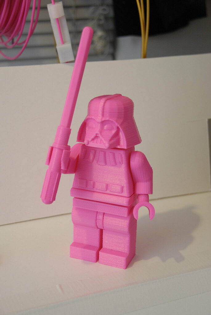
My biggest project to date has in fact been the awesome Giant lego Darth Vader model from thingiverse, in pink:


This is also my first commission, got another to do in black when the filament arrives next week - great fun!

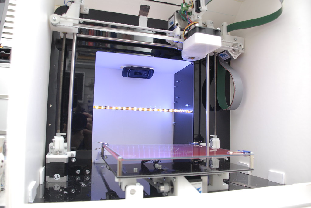
The foamboard heated chamber is working well, but I tend to leave the top flap open to stop it getting too warm.  I've also finished playing with my custom start/end gcode for slic3r:

Start G-Code
M104 S0
M83
M140 S80
G28
G1Y98F9000
M190 S80
G1X5Y98Z150F9000
M104 S210
G1X5Y98Z1F9000
G1Z0.05
M109 S210
G1Z5
G1X15


End G-Code
M103
M108 S50.0
M113 S0.0
M104 S0
M140 S0
M106
G1X0Y0F9000
G91
G1Z20
G90
M84
M190 S0
G4 P200000
M83
G28
M84
M107

Which is making for very reliable prints.  I am still getting the odd part warping up at the corners and don't feel confident printing full plates, but then I also need to get some pure acetate to clean the glass, so that's probably a contributing factor.

I've also been somewhat paranoid about leaving the printer unattended, so installed an LED light strip and a webcam.  I then run a livestream feed during prints, which I can monitor on pretty much any device (ipad, blackberry, iphone, etc) - surreal moment this afternoon when I found myself watching a print on my wife's android phone whilst at a softplay with my kids!


I have a more complex project almost complete - a DSLR follow focus unit - which I'll post about when it's been properly tested.


Sunday, 3 March 2013

Mendel90 - Heated Build Chamber from Foamboard

I've been steady printing small parts for the last few weeks, but since changing to a new reel of filament (Crystal Clear 3mm from faberdashery), I've been struggling to get reliable print settings.  This has been very frustrating, as the reel of Village Green that nophead supplied in the Mendel90 kit was very reliable.

In case anyone is interested - my settings are currently:

  • Hot end: 200C first layer, 180C thereafter
  • Bed: 90C first layer, 80C thereafter
  • Everything else at Slic3r defaults (everything I tweak seems to make it worse)

One particularly frustrating problem has been large prints curling up at the corners, or failing to stick to the heated bed.  Ambient temperatures in my office have been pretty cold lately, which won't help.  So...  it seemed a good idea to build an enclosure around the Mendel90 to keep it cosy.

I had some spare foamboard which seemed like an ideal material to build the enclosure from.  I also added a 2mm glass sheet to the front (a piece of picture frame glass, approx £3) which can be slid in/out vertically by lifting the flap along the front edge.  I've only been running with it for a few hours, but it's certainly allowed me to print some larger parts that weren't possible before.  Will find a thermometer soon and check the temperature it reaching, but at a guess, I'd say it's in the 30-40 degree range.


Filament is fed through a long slit in top, the slit is covered in thin craft foam to keep the heat in and trap dust.  The foamcore is joined to itself with hotglue and to the Mendel90 with white duct tape.


I'm fairly pleased with how it turned out - it was quick to build, very cheap and appears to do the job - it doesn't even look that bad.

Alongside building an enclosure, I also put together a quick filament spool:


It's similar to many already on Thingiverse, but uses cheap aluminium tube and very lightweight parts - 6mm tube for the arms, 12mm tube for the axle (no bearings). On Thingiverse - http://www.thingiverse.com/thing:56694


PS - while writing this I've been playing with the custom start GCode in Slic3r, and now appear to have a clogged hotend - just stopped a print as no plastic was coming out to discover it appears to be leaking out above the nozzle - crap :(

Here's the startup GCode that killed it...  derived from nophead's oozefree start


M83
G28
G1Y98F9000
G1X5Y98Z1F9000
G1Z0.05
M190 S90
G4 P120000
M109 S200

Sunday, 3 February 2013

Mendel90 - First prints

After watching Nophead's Mendel90 design evolve over the last year, I went for an impulse buy of the full kit a few weeks ago... the parts arrived Thursday and I've spent the weekend getting it assembled. The kit is superb, great attention to detail, good instructions and everything you need to get printing in one box - backed by top notch service from Nophead and his wife. I would highly recommend the kit to anyone wanting to get stuck into 3D printing - it's much easier to put together than a Prusa Mendel and the final machine looks amazing with the black dibond finish. Only slight surprise is just how big it is, occupying a fair chunk of space on my desk.


 The manual is very well written, with just a few bits which weren't immediately obvious - but a quick google for Mendel90 images quickly cleared those up. The setup steps all went very smoothly, and after just a couple of calibration prints, the Mendel90 had printed the Android test model. This afternoon (Sunday) has been spent printing random objects for the kids, including:

  • A couple of Nerf targets, inspired by http://www.thingiverse.com/thing:14666 - I knocked these up in OpenSCAD, with the open mk2 design being my favourite.
  • Two hairclips for my daughter based on: http://www.thingiverse.com/thing:29185
  • A belt clip for my son's wooden sword
  • 5 segments from the modular hose (ala loc line) OpenSCAD library I put together a year or so ago (!) - good news is they worked after a small tweak to the library to solve a non-manifold issue...  http://www.thingiverse.com/thing:9457
Pictures of these first prints below:


I can safely say, I'm addicted - and fortunately so are my family...  the ability to dream up a part, model it, print it and then play/use it in an afternoon is just incredible :)


Thursday, 17 January 2013

Variable density circle packing to approximate bone cross section - WIP 1

Currently looking into generating infill patterns for 3D printing that have variable density and an internal structure similar to bone. Been pondering this one for over a year, but finally got round to writing some code.

First stage in this process is to develop a robust sphere packing algorithm, the spheres will later be "sliced" in some way to generate the infill. Not sure what I'll try first, but perhaps a veronoi tessellation followed by printing each face of the resulting tessellation. Short cut may be to merge the spheres back into an existing model (via OpenSCAD, or directly modifying the STL) and then slicing as per normal... along the lines of Gary's experiment: thoughts-on-fill-algorithms/

For now, the short video below shows the WIP algorithm operating in 2D (as it's easier to debug before moving into 3D).

High level algorithm models the cells as soft-bodies, with a repelling force acting between close neighbours. The repelling force is non-linear, with a sharp drop-off at the cells "boundary". Cells start small and attempt to grow to a target radius based on their distance from the boundary of the object. Cells undergo mitosis (split into two) under certain conditions: 1) they have no close neighbours 2) there is a sufficient gap (3 units in the demo video) between the cell and all of it's neighbours.

For each iteration of the algorithm:
1) inter-cell forces are calculated
2) cell locations are updated, taking into account collisions with other cells (soft collision) and the object boundary (nullifies velocity component orthogonal to the boundary)
3) mitosis conditions are evaluated, cell splits if appropriate
4) cell updates it's radius based on distance to neighbours (e.g. only grows if there's room)

Video is showing every iteration of the algorithm - it runs much faster in real time, but performance judgements are not really relevant yet, as it's far from optimised and only in 2D. Key challenge is a robust way of judging the end of the convergence...


Sunday, 5 February 2012

Variable Density Hilbert Curve

First few images from a quick proof of concept, but first the background... I've been pondering infill algorithms for a while and wondering how best to account for variable internal density, whilst still retaining high print speed. Whilst looking at space filling curves yesterday, it occurred to me that it should be possible to vary the apparent density of the curve simply by modifying the recursion depth inline with a reference model or image.

To quickly judge the effectiveness of this approach, I've put together a very quick applet that varies the recursion density of the Hilbert Curve according to the average grayscale levels of a reference image. Below are a couple of samples to illustrate the effect.

 1) Rubix Cube - Hilbert Curve between 4 and 8 levels of recursion:


2) Kitten - Hilbert Curve between 6 and 9 levels of recursion

3) Kitten - Hilbert Curve between 5 and 9 levels of recursion

The two kitten images show the effect of modifying a "contrast" operator, that controls the level of recursion associated with each grayscale range.

Next step is to see what happens if this approach is combined with a density map generated along the lines of this post: http://axuv.blogspot.com/2012/01/adaptive-infill.html. Off to Amsterdam for a few days, so this will have to wait for next weekend...

Tuesday, 31 January 2012

Bezier Curves with Marlin - Video

Quick video showing a "monster", rammed with bezier curves, being printed via modified Marlin firmware.

Monday, 30 January 2012

Bezier curves with Marlin

Fixed it! Not sure why, but adding a ClearToSend() after processing the G5 code has sorted the weird hanging issue. Ran a quick test drawing a fairly complex monster with loads of bezier curves (converted from an SVG I found online) and it is very impressive. Watching a pen zip round the curves at one hell of a pace has left a great big grin on my smug mug. Good place to call it quits and get some sleep... will try and post a video of it in action tomorrow.

Guess this means I'll have to look at adding bezier curve path smoothing to Slic3r - at least I can start with the arc detection as a basis. Least squares and Newton-Raphson, yummy.

Extruder and hot end assembly

Well, it's certainly been a while since my last post, but after an extremely hectic finish to last year, including transitioning to a new role in another function (!), things have finally settled down enough for me to make some progress on the build.

Over the last week or so, I've put together the Wade's extruder from the thingfarm kit I bought last year. I've also started assembly the J Head Nozzle (MKI), also from thingfarm. It's been a slow process, as I've only had the odd few minutes to spare and keep finding little bits that I need to progress. The most recent was discovering the fire cement I bought to fit the power resistor is useless (far too grainy) and instead opted for some rope seal adhesive (off the back of a hophead recommendation in the forums), which turned out to work a treat.

Installing the two M3 screws in the grove mount hasn't gone quite so well.... I clamped the hot end into the extruder, drilled the holes to 2.5mm and then discovered my taps have gone missing :( Being an impatient sod, I figured I'd just drill out the holes a little and see if the M3 bolts would self tap. It kind of worked - the hot end is held rock firm, however, the bolts got pushed outwards by the peek and have ended up, well, wonky is probably the most gracious way to describe it. In conclusion, looks shoddy, but does the job. No doubt something I can remedy at some point .

Can't do much more tonight, as the rope seal adhesive is still setting, but next step is to wire up the hot end and extruder stepper, then see if the whole shebang works!

As a mild distraction, I couldn't hold out any longer and bought an iMac just after the New Year. While looking for any excuse to use it, I took the opportunity to get the Marlin firmware installed, the latest version of Pronterface and slic3r. I've also started incorporating the bezier code I wrote into the Marlin firmware, something I'd meant to do last year, but never got to it. The first quick hack almost works, however, it seems to randomly hang for approx 10sec after processing a bezier curve g-code. Have spent an hour or so trying to debug it with no joy... very annoying, as I can't see any real difference between how the bezier code works vs the arc code. Grr. No doubt will figure it out after a few more hours digging.

Times like this I wish I had an in-circuit debugger...

Wednesday, 17 August 2011

Curve fitting

I've shelved the SVG conversion code for now, as although it's a fun challenge, it's somewhat worthless longer term.

I see my next few activities as:
- Develop a GCode pre-processor that sits between Skeinforge and the printer host, which will convert incoming continuous paths into splines
- Add an acceleration calculation into the pre-processor to provide acceleration "hints" to the firmware
- Modify firmware to support acceleration hints, with graceful degradation to current acceleration algorithm
- Implement tolerance-driven path smoothing to the pre-processor

Might take a while to get through all that, but I've made a start tonight by working up a basic algorithm to take a sequence of linear line segments and convert them to a sequence of bezier curves using a modified form of the Finite Difference approach from http://en.wikipedia.org/wiki/Cubic_Hermite_spline. Currently it smooths all segments, but next I'll add an inter-segment angle calculation and only smooth segments with a small angle (perhaps <10 degrees). Then just need to wire that to a GCode parser and that should yield a functioning, albeit very simplistic, pre-processor.


Monday, 15 August 2011

Drawing a Prusa

Minor update this evening...

Extended the "tool" support for the bezier G5 code by adding visualisation support for the curves in Pronterface - also added relative co-ordinate support to the visualisation (both actually implemented in gviz.py). Then felt the need to stress test the code, so vectorised one of Gary Hodgson's Prusa images and ran it through the mill...


Sorry about the poor quality video, couldn't face waiting for an HD version to upload (must find a way to edit the MOV files my camera produces, otherwise even a short clip can be 400MB sad smiley )

Hello World with Bezier Curves

Spent the last week working on a java applet to convert SVG to GCode, incorporating my new G5 code for cubic bezier curves. As of this evening, the conversion process will take basic curves from Inkscape and convert them to functional GCode! After a bunch of tests, I figured it was time to film something and share it... what better than "Hello World"


That's right folks - a reprap printing a complex set of bezier curves, with all the complex stuff happening in the modified Sprinter firmware!


The conversion process is working pretty well, need to improve transform support and some more of the SVG path primitives to make it more robust/flexible. I'm starting to hate the SVG standard - it's a real half-way cop out between a bespoke language and XML. What's the point in using XML to encode image data, if you then bail on the critical stuff and encode complex paths/transforms in attributes using a completely different (and fairly complex) syntax!

Of course, I might get distracted by building the extruder/hot-end, but if not, then I'll also be taking another look at how to make the acceleration code play nice with curves.