I've shelved the SVG conversion code for now, as although it's a fun challenge, it's somewhat worthless longer term.
I see my next few activities as:
- Develop a GCode pre-processor that sits between Skeinforge and the printer host, which will convert incoming continuous paths into splines
- Add an acceleration calculation into the pre-processor to provide acceleration "hints" to the firmware
- Modify firmware to support acceleration hints, with graceful degradation to current acceleration algorithm
- Implement tolerance-driven path smoothing to the pre-processor
Might take a while to get through all that, but I've made a start tonight by working up a basic algorithm to take a sequence of linear line segments and convert them to a sequence of bezier curves using a modified form of the Finite Difference approach from http://en.wikipedia.org/wiki/Cubic_Hermite_spline. Currently it smooths all segments, but next I'll add an inter-segment angle calculation and only smooth segments with a small angle (perhaps <10 degrees). Then just need to wire that to a GCode parser and that should yield a functioning, albeit very simplistic, pre-processor.
Wednesday, 17 August 2011
Monday, 15 August 2011
Drawing a Prusa
Minor update this evening...
Extended the "tool" support for the bezier G5 code by adding visualisation support for the curves in Pronterface - also added relative co-ordinate support to the visualisation (both actually implemented in gviz.py). Then felt the need to stress test the code, so vectorised one of Gary Hodgson's Prusa images and ran it through the mill...
Sorry about the poor quality video, couldn't face waiting for an HD version to upload (must find a way to edit the MOV files my camera produces, otherwise even a short clip can be 400MB sad smiley )
Extended the "tool" support for the bezier G5 code by adding visualisation support for the curves in Pronterface - also added relative co-ordinate support to the visualisation (both actually implemented in gviz.py). Then felt the need to stress test the code, so vectorised one of Gary Hodgson's Prusa images and ran it through the mill...
Sorry about the poor quality video, couldn't face waiting for an HD version to upload (must find a way to edit the MOV files my camera produces, otherwise even a short clip can be 400MB sad smiley )
Hello World with Bezier Curves
Spent the last week working on a java applet to convert SVG to GCode, incorporating my new G5 code for cubic bezier curves. As of this evening, the conversion process will take basic curves from Inkscape and convert them to functional GCode! After a bunch of tests, I figured it was time to film something and share it... what better than "Hello World"
That's right folks - a reprap printing a complex set of bezier curves, with all the complex stuff happening in the modified Sprinter firmware!
The conversion process is working pretty well, need to improve transform support and some more of the SVG path primitives to make it more robust/flexible. I'm starting to hate the SVG standard - it's a real half-way cop out between a bespoke language and XML. What's the point in using XML to encode image data, if you then bail on the critical stuff and encode complex paths/transforms in attributes using a completely different (and fairly complex) syntax!
Of course, I might get distracted by building the extruder/hot-end, but if not, then I'll also be taking another look at how to make the acceleration code play nice with curves.
That's right folks - a reprap printing a complex set of bezier curves, with all the complex stuff happening in the modified Sprinter firmware!
The conversion process is working pretty well, need to improve transform support and some more of the SVG path primitives to make it more robust/flexible. I'm starting to hate the SVG standard - it's a real half-way cop out between a bespoke language and XML. What's the point in using XML to encode image data, if you then bail on the critical stuff and encode complex paths/transforms in attributes using a completely different (and fairly complex) syntax!
Of course, I might get distracted by building the extruder/hot-end, but if not, then I'll also be taking another look at how to make the acceleration code play nice with curves.
Friday, 12 August 2011
Native cubic bezier curves for Sprinter
Started a new thread on the reprap forums to track the development of some new Sprinter capability - namely the addition of a new GCode for cubic bezier curves. See the thread for more details:
http://forums.reprap.org/read.php?147,93577
Will post a video soon
http://forums.reprap.org/read.php?147,93577
Will post a video soon
Tuesday, 2 August 2011
Sierpinski Curve at 150mm/s
Since my last post, I've been working towards getting the core electronics finished, all axes tested and a getting fully functional toolchain setup.
Having got the Y axes moving, I went on to wire in the X and Z steppers. Then expand my little test sketch to do a couple of back/forth moves on each axes to check everything was running smoothly:
This went fairly smoothly, but the Z axis bearings were sticking. I went for the same "fix" as for the other axes and cleaned the rods with a wet wipe and then smeared some lithium grease. That made a big improvement, but it stills needs a weight on the idler end, otherwise it won't slide down under gravity alone. Not a big issue for now, and I'm vaguely hoping the bearings will wear in after a bit of use.
Next was soldering and fitting the Opto Endstops. The kit/instructions from Traumflug were excellent and went together without issue. Fitting the actual sensor was easy enough, but my current solution for the flags is extremely crude - will definitely improve this at some point, but it will do for now. As I fitted each endstop, I extended my sketch to include a set of homing tests:
At this point I couldn't resist doing some speed tests and discovered that the Z axes feedrate is severely limited due to the very low Pololu drive current. I don't want to turn the current up until I've added heatsinks, so got on and ordered a set of 8 off ebay - a bargain at £1.74, but given they are coming from China I'm only half expecting them to arrive.
Once all the endstops were working, it was time to install some proper firmware. I've settled on the latest version of Sprinter, this was after reading up on peoples comments on the various mature firmwares and also after skimming the source code repositories for each. Overall I was impressed with the apparent performance, feature set and also simplicity of the source for Sprinter.
Because of limited cable length, my X and Z stepper motor pins are swapped vs normal RAMPS config, but I had already created a variant of the pins.h for my test sketch, so it was a simple matter to copy that over and upload the firmware.
To test everything, I thought I'd try out Kliment's Pronterface script from the Python Printrun host software - worked an absolute treat and had axRap dancing to G Codes in minutes.
After a while of playing with hand-coded G Code files, I decided it was time to try a more challenging stress test. Rather than jump straight to Skeinforge, etc - I decided to tape a pen to the carriage and play with drawing some pictures. First up was more hand coded G Code to draw basic shapes, but then I struck on the idea of generating G Code for a basic fractal...
That quickly lead to the infamous Sierpinski Curve, which has a nice little Java applet on the associated wikipedia page. A little hacking and I had the script generating nicely scaled/translated G Code, with a little bit of header/footer code to home axes, set feedrate, etc. Here it is printing the 3rd level of recursion at 150mm/s - you'll need to watch full-screen to see the red ink!:
By this point it was very late Sunday night (hence the poor quality video) and time to call it quits. Mission for this week is to build the extruder, hot-end and mount the heated bed - all the missing parts arrived last week, so just need the time to focus!
I also ordered a reel of PLA last night and picked up some Fire Cement from B&Q, so nothing left to order/buy before my first print - can't wait! :)
Having got the Y axes moving, I went on to wire in the X and Z steppers. Then expand my little test sketch to do a couple of back/forth moves on each axes to check everything was running smoothly:
This went fairly smoothly, but the Z axis bearings were sticking. I went for the same "fix" as for the other axes and cleaned the rods with a wet wipe and then smeared some lithium grease. That made a big improvement, but it stills needs a weight on the idler end, otherwise it won't slide down under gravity alone. Not a big issue for now, and I'm vaguely hoping the bearings will wear in after a bit of use.
Next was soldering and fitting the Opto Endstops. The kit/instructions from Traumflug were excellent and went together without issue. Fitting the actual sensor was easy enough, but my current solution for the flags is extremely crude - will definitely improve this at some point, but it will do for now. As I fitted each endstop, I extended my sketch to include a set of homing tests:
At this point I couldn't resist doing some speed tests and discovered that the Z axes feedrate is severely limited due to the very low Pololu drive current. I don't want to turn the current up until I've added heatsinks, so got on and ordered a set of 8 off ebay - a bargain at £1.74, but given they are coming from China I'm only half expecting them to arrive.
Once all the endstops were working, it was time to install some proper firmware. I've settled on the latest version of Sprinter, this was after reading up on peoples comments on the various mature firmwares and also after skimming the source code repositories for each. Overall I was impressed with the apparent performance, feature set and also simplicity of the source for Sprinter.
Because of limited cable length, my X and Z stepper motor pins are swapped vs normal RAMPS config, but I had already created a variant of the pins.h for my test sketch, so it was a simple matter to copy that over and upload the firmware.
To test everything, I thought I'd try out Kliment's Pronterface script from the Python Printrun host software - worked an absolute treat and had axRap dancing to G Codes in minutes.
After a while of playing with hand-coded G Code files, I decided it was time to try a more challenging stress test. Rather than jump straight to Skeinforge, etc - I decided to tape a pen to the carriage and play with drawing some pictures. First up was more hand coded G Code to draw basic shapes, but then I struck on the idea of generating G Code for a basic fractal...
That quickly lead to the infamous Sierpinski Curve, which has a nice little Java applet on the associated wikipedia page. A little hacking and I had the script generating nicely scaled/translated G Code, with a little bit of header/footer code to home axes, set feedrate, etc. Here it is printing the 3rd level of recursion at 150mm/s - you'll need to watch full-screen to see the red ink!:
By this point it was very late Sunday night (hence the poor quality video) and time to call it quits. Mission for this week is to build the extruder, hot-end and mount the heated bed - all the missing parts arrived last week, so just need the time to focus!
I also ordered a reel of PLA last night and picked up some Fire Cement from B&Q, so nothing left to order/buy before my first print - can't wait! :)
Sunday, 24 July 2011
Y Axis works!
Thought I'd kick things off this evening by connecting up the Y-axis motor and writing a short sketch to drive the stepper back and forth a few times - simple right? Wrong.
Connecting the stepper was easy enough, writing the sketch was easy enough - but would the motor move - oh, no... not a chance. So, having traced pin assignments, double-checked code, read through the Sprinter firmware, several tutorials on adruino/stepper combos, fiddling with Pololu driver current and finally rebuilding the connector for the motor, I finally found the issue.
*drum roll*
The Pololu enable pins are inverted - low to enable, not high! In my haste to write that little sketch, I missed that little fact and have summarily wasted the rest of the evening - smeg. On the up side, I found this little tutorial on assembling servo connectors:
http://www.rchelisite.com/how_to_crimp_servo_plugs.php
Which helped a great deal, as it turns out my first attempt was a criminal bodge compared to how it should be done - I'm sure I used to know how to do this stuff, but apparently it's been too long.
Having got the enable pin the right way round, everything works perfectly. I even took a few minutes to make the sketch accelerate the motor at the beginning/end of each move just for kicks... makes the motor sing a little tune as it moves :)
Now I'm knackered, so must sleep and will have to wait another day to get the rest of axes wired :(
PS - will youtube a video tomorrow and post the sketch in case anyone else might find it useful
Connecting the stepper was easy enough, writing the sketch was easy enough - but would the motor move - oh, no... not a chance. So, having traced pin assignments, double-checked code, read through the Sprinter firmware, several tutorials on adruino/stepper combos, fiddling with Pololu driver current and finally rebuilding the connector for the motor, I finally found the issue.
*drum roll*
The Pololu enable pins are inverted - low to enable, not high! In my haste to write that little sketch, I missed that little fact and have summarily wasted the rest of the evening - smeg. On the up side, I found this little tutorial on assembling servo connectors:
http://www.rchelisite.com/how_to_crimp_servo_plugs.php
Which helped a great deal, as it turns out my first attempt was a criminal bodge compared to how it should be done - I'm sure I used to know how to do this stuff, but apparently it's been too long.
Having got the enable pin the right way round, everything works perfectly. I even took a few minutes to make the sketch accelerate the motor at the beginning/end of each move just for kicks... makes the motor sing a little tune as it moves :)
Now I'm knackered, so must sleep and will have to wait another day to get the rest of axes wired :(
PS - will youtube a video tomorrow and post the sketch in case anyone else might find it useful
Saturday, 23 July 2011
It's Alive...
A few hours this evening, and the odd burst over the last two weeks mean the axRap now has a brain and beating heart.
It began on dark, mild night when the organs of an old ShuttleX SSG were removed...
Dragged back to the lab under cover of darkness, the heart of the shuttle was stripped down to the bare essentials...
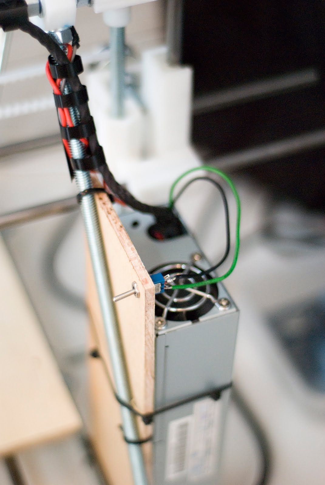
All surplus connections were removed, the auto-sense connection soldered onto the bleeding stump where the 3.3V wires used to be. Power-ok (gray) and a 5v line were kept for a possible future application. Power-on (green) and a ground were connected to an old toggle switch then everything was sewn back together by hand...
Then it was time for the saw, at it's mercy was some left-over 6mm plywood from the bottom plates. A few quick strokes, a flurry of the bone drill and a makeshift cradle for the heart was ready...
With the Shuttle's blood barely dry on my hands, I turned my attentions to the brain. A further application of saw, drill and heavy duty threads produced the base of a cranium - with cooling fan. Arteries were laid in, held in protective spiral bindings, and with a flick of the switch I bestowed animation upon this lifeless matter. Admittedly, the animation was merely the drone of a cooling fan, but still - it's progress.
Given it's 1am, I need to get some sleep - so connecting the first of the stepper motors will have to wait until tomorrow. Before I sleep again, I'm hoping to have at least one axis moving under Sprinter firmware, including an endstop.
It began on dark, mild night when the organs of an old ShuttleX SSG were removed...
Dragged back to the lab under cover of darkness, the heart of the shuttle was stripped down to the bare essentials...
All surplus connections were removed, the auto-sense connection soldered onto the bleeding stump where the 3.3V wires used to be. Power-ok (gray) and a 5v line were kept for a possible future application. Power-on (green) and a ground were connected to an old toggle switch then everything was sewn back together by hand...
Then it was time for the saw, at it's mercy was some left-over 6mm plywood from the bottom plates. A few quick strokes, a flurry of the bone drill and a makeshift cradle for the heart was ready...
With the Shuttle's blood barely dry on my hands, I turned my attentions to the brain. A further application of saw, drill and heavy duty threads produced the base of a cranium - with cooling fan. Arteries were laid in, held in protective spiral bindings, and with a flick of the switch I bestowed animation upon this lifeless matter. Admittedly, the animation was merely the drone of a cooling fan, but still - it's progress.
Given it's 1am, I need to get some sleep - so connecting the first of the stepper motors will have to wait until tomorrow. Before I sleep again, I'm hoping to have at least one axis moving under Sprinter firmware, including an endstop.
Subscribe to:
Posts (Atom)